Aluminum Foil for LAN & Communication Cable Shielding in 10Gb Ethernet: A Distinctive Materials-First Perspective
When network designers talk about 10Gb Ethernet performance, the conversation usually centers on frequency, insertion loss, and crosstalk. Yet beneath those electrical metrics lies a quiet hero: the aluminum foil tape wrapped around the cable core. For high‑speed LAN and communication cables, especially 10GBASE‑T and 10Gb industrial Ethernet, the specific aluminum alloy, temper, thickness, and lamination structure make the difference between a marginal design and a robust, standards‑compliant solution.
Why 10Gb Ethernet Cables Demand Higher‑Spec Aluminum Foil
Traditional Fast Ethernet and even standard Cat5e applications could tolerate more variability in foil composition and thickness. For 10Gb Ethernet over twisted pair (Cat6A and above), the demands intensify:
- Higher operating frequencies, typically tested up to 500 MHz and designed with headroom
- More stringent alien crosstalk limits
- Greater sensitivity to common‑mode noise and external EMI
At these bandwidths, the shielding foil is no longer just a mechanical wrap. It acts as a controlled, continuous conductive barrier whose surface conductivity, skin depth, and bonding integrity directly affect:
- Transfer impedance
- Shielding effectiveness over frequency
- Grounding continuity along the cable length
That is why careful selection of aluminum alloy series (commonly 1xxx and 8xxx), temper (O, H18, H19, etc.), foil thickness, and lamination scheme (AL/PET, AL/PET/AL, AL/PET/PE, etc.) becomes critical to stable 10Gb performance in real‑world EMI environments.
Alloy Choice: Why Foil Chemistry Matters for Signal Integrity
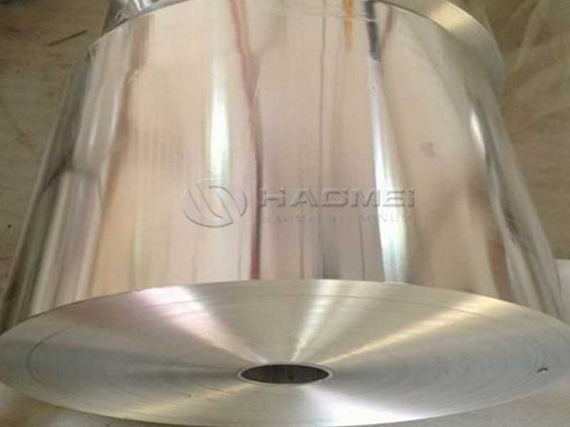
From a materials standpoint, aluminum foil for cable shielding is typically supplied in either:
- 1xxx series: high‑purity aluminum with excellent conductivity, ideal where low resistance and high shielding efficiency are prioritized
- 8xxx series: Al‑Fe‑Si or similar alloys offering better mechanical strength, improved formability, and stable processing for ultra‑thin gauges
For 10Gb Ethernet cables, the design trade‑off is subtle. High‑purity 1xxx alloys maximize conductivity and minimize transfer impedance, yet 8xxx alloys provide better handling at ultra‑thin thicknesses (down to about 6–8 μm) without pinholes or tearing during slitting and wrapping.
A typical balance for high‑quality 10Gb LAN shield foil is:
- Using 8xxx series aluminum for overall cable shields where mechanical robustness and processing stability are critical
- Using 1xxx or high‑conductivity 8xxx where drain‑wire contact resistance and overall shield continuity must be minimized
The alloy chemistry also affects oxide layer behavior and corrosion resistance, which in turn influences long‑term contact resistance between foil and drain wire, especially in humid or temperature‑cycled environments.
Tempering: Mechanical State Tailored for Cabling Processes
The temper of the aluminum foil defines its mechanical hardness, yield strength, and elongation. In cable manufacturing, this determines how the foil behaves during:
- Forming and wrapping around twisted pairs or overall core
- Bending and flexing during installation and service
- Lamination adhesion to polymer films
Soft temper (O):
- Excellent flexibility and conformability
- Better coverage around small bending radii and twisted pairs
- Lower risk of micro‑cracking in long‑term flexing
Hard temper (H18 / H19):
- Higher strength and improved dimensional stability during slitting and high‑speed wrapping
- Better crease memory, which helps maintain overlap integrity
- Slightly more fragile under repeated sharp bending if not properly laminated
For 10Gb Ethernet applications, a hybrid approach is often used. The metallic core is produced in a harder temper (such as H18/H19), then laminated to PET or other polymers, which provide additional flexibility and prevent crack propagation. The finished laminate behaves “softer” than the bare metal while preserving the dimensional accuracy of a hard‑tempered foil.
Thickness, Skin Depth, and Shielding Effectiveness
The thickness of the aluminum layer in shielding foil is not arbitrary. For 10Gb signals, the relevant EMI frequencies typically extend into the hundreds of MHz. Aluminum’s skin depth δ at 100 MHz is on the order of micrometers, much smaller than even very thin foil. This means that as long as the aluminum layer is continuous and defect‑free:
- Increasing thickness beyond about 15–25 μm offers diminishing EMI shielding returns
- Primary gains from additional thickness relate more to mechanical robustness than to basic electromagnetic shielding
Common aluminum layer thicknesses for LAN and communication cable foils are in the range of about 6–25 μm, often around 7–12 μm for inner shields and slightly thicker for overall shields in harsh environments. The is achieving:
- Sufficient conductivity for low transfer impedance
- Continuous coverage with no pinholes
- Stable mechanical behavior in lamination and cabling
This is why alloy and temper control matter: they allow manufacturers to go thinner while maintaining structural integrity, which saves weight and cost without compromising EMC performance.
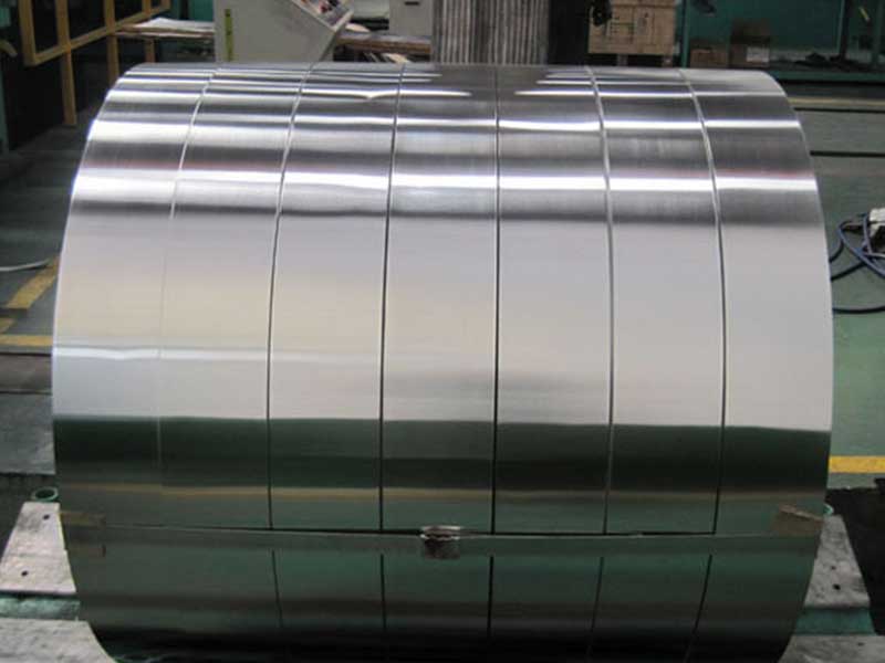
Laminated Structures: Beyond Bare Metal
Bare aluminum ribbon would be too fragile and prone to cracking and corrosion in a cable environment. The solution is to create a multilayer laminate that integrates aluminum foil with polymer films. For 10Gb Ethernet LAN cables, the most common structures include:
- AL/PET: Aluminum bonded to polyester; the PET provides tensile strength and dielectric separation from cores
- AL/PET/AL: Dual‑side aluminum layers for enhanced shielding and balanced structure; used in high‑EMI or critical data applications
- AL/PET/PE or AL/PET/PP: Additional outer polyolefin layer for improved heat sealing or compatibility with jacket materials
From a distinctive materials viewpoint, the polymer layer is not just “backing”; it is a mechanical and dielectric partner to the aluminum:
- The PET thickness and modulus define the minimum bend radius without delamination
- The adhesion system determines whether shield resistance stays stable over time
- The combination of aluminum and polymer influences the propagation of micro‑cracks under flexing
For 10Gb LAN cable shielding, typical PET film thickness ranges from about 8 to 25 μm, selected according to the cable category, bend radius requirements, and processing speed on the cabling line.
Standards and Performance Alignment
While aluminum foil itself is not directly covered by Ethernet standards, it is engineered to support cables that must meet:
- IEEE 802.3an and related 10GBASE‑T requirements
- ISO/IEC 11801, ISO/IEC 61156 series for balanced communication cables
- TIA/EIA‑568 standards for structured cabling (Cat6A, Cat7, Cat7A, and beyond)
To ensure the foil enables compliance, critical performance metrics on the material and laminate level typically include:
- Electrical resistivity consistent with aluminum alloy standards such as EN or ASTM for 1xxx and 8xxx series
- Dimensional tolerances in thickness and width tight enough to maintain uniform shielding overlap
- Adhesion strength between aluminum and PET film suitable for high‑speed longitudinal or helical wrapping
- Corrosion resistance and stability of surface oxide under elevated temperature and humidity
For shielded twisted‑pair (STP, FTP, S/FTP) and high‑end F/UTP 10Gb cables, these parameters must be optimized not only to meet initial type tests but to preserve performance over the cable’s lifetime under installation stresses and environmental exposure.
Mechanical and Electrical Interaction: A Systems View
Viewing shield foil as a system component rather than just a commodity strip reveals interactions that affect 10Gb performance in subtle ways:
- The drain wire is designed to ride against the metallic surface of the foil. Alloy purity and surface finish influence the long‑term stability of the contact resistance.
- The overlap of the foil wrap forms a longitudinal seam. Temper and laminate stiffness define whether that seam stays closed under bending and torsion, impacting shielding continuity.
- The dielectric properties of the polymer backing influence the local capacitance to neighboring pairs, which can affect crosstalk in tightly packed cable designs.
Optimized aluminum foil for 10Gb Ethernet is therefore a tuned combination of:
- Adequate conductivity and uniform thickness to keep transfer impedance low and predictable
- Temper and alloy that balance mechanical strength with flex durability
- Lamination receivers (PET, PE, etc.) that support cable forming, twisting, and operating bend radii
Typical Parameter Ranges for 10Gb Ethernet Shielding Foil
The exact specifications are tailored to a customer’s cable design, but typical ranges for high‑performance LAN and communication cable shielding foils include:
- Alloy type: 1xxx or 8xxx series
- Temper: O, H18, H19 depending on forming and strength requirements
- Aluminum thickness: approximately 6–25 μm, often around 7–12 μm for pair shields and 10–20 μm for overall shields
- PET thickness: approximately 8–25 μm
- Standard widths: customized to cable design, optimized for longitudinal or helical wrapping with defined overlap
Within these ranges, more demanding 10Gb and higher‑category cables often favor tighter tolerances, higher purity, and better lamination adhesion to ensure consistent EMC performance.
Chemical Composition and Material Properties Table
Below is an example of a commonly used 8xxx‑series cable shielding foil alloy with typical composition and physical properties. Exact values vary by specification and melt practice, but this illustrates the controlled nature of the material behind a “simple” foil.
Typical Chemical Composition and Properties (Representative 8000‑Series Aluminum Foil for LAN Shielding)
| Parameter | Typical Value / Range | Notes |
|---|---|---|
| Alloy designation | 8xxx series (Al‑Fe‑Si type) | Optimized for foil applications |
| Al content | Balance | Primary matrix |
| Fe | About 0.5–1.2 wt% | Strength and foilability |
| Si | About 0.3–1.0 wt% | Improves processability |
| Cu | ≤ 0.1 wt% | Controlled for conductivity and corrosion |
| Mn | ≤ 0.2 wt% | Optional for strength refinement |
| Mg | ≤ 0.05 wt% | Kept low to maintain foil workability |
| Zn | ≤ 0.1 wt% | Limited to preserve corrosion behavior |
| Ti | ≤ 0.05 wt% | Grain refinement |
| Other each | ≤ 0.05 wt% | Traces controlled |
| Other total | ≤ 0.15 wt% | |
| Temper | O / H18 / H19 | Selected per cable design |
| Tensile strength (H18) | About 90–130 MPa | Depending on gauge and processing |
| Elongation (H18) | About 1–4 % | Higher in O temper |
| Electrical conductivity | About 34–37 MS/m | Slightly below pure 1xxx, but stable |
| Density | About 2.70 g/cm³ | Stable for weight calculations |
| Melting range | Approximately 640–660 °C | Typical for Al‑based alloys |
| Surface oxide | Natural Al₂O₃ thin film | Contributes to corrosion resistance |
| Corrosion resistance | Good in typical cable environments | Enhanced by lamination and jackets |
For applications requiring maximum conductivity, a high‑purity 1xxx series foil can be used, with aluminum content typically above 99.0–99.5 percent and electrical conductivity in the range of about 36–38 MS/m or higher, at the cost of somewhat lower mechanical strength in the same thickness.
Implementation Conditions for Reliable 10Gb Shielding
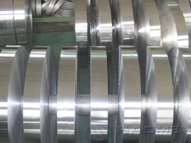
To translate good foil specifications into cable‑level performance, several process conditions must be coordinated between foil supplier and cable manufacturer:
- Slitting must preserve edge quality to avoid tears that propagate during wrapping.
- Wrapping tension must be matched to foil temper and laminate stiffness to prevent wrinkling or over‑stretching.
- Overlap width must be maintained consistently along the cable to ensure continuous shielding; this depends on foil width tolerance and lamination flatness.
- Thermal profiles in subsequent cable manufacturing steps (such as jacket extrusion) must remain within the thermal limits of the laminate to avoid adhesion loss or foil buckling.
In a well‑designed 10Gb cable, the foil’s material data sheet is not an afterthought; it is integrated into the cable’s mechanical and EMC design process from the outset.
From this viewpoint, aluminum foil in LAN and communication cable shielding is closer to a precision EMC component than a simple packaging material. Each attribute — alloy composition, temper, thickness, lamination, surface state — is chosen to manage electromagnetic fields, mechanical stresses, and environmental exposure throughout the 10Gb Ethernet cable’s lifecycle.
When specified and produced correctly, shielding foil:
- Enables Cat6A, Cat7, and higher‑category cables to meet stringent IEEE and ISO/IEC requirements
- Maintains low transfer impedance and strong shielding effectiveness well into the high‑MHz range
- Supports flexible, reliable installation without micro‑cracking or delamination
Treating aluminum foil as a strategic engineered material rather than a generic strip is what allows modern high‑speed LAN and communication cables to carry 10Gb signals cleanly, reliably, and efficiently in increasingly noisy electromagnetic environments.