Aluminum Foil for Cable Shielding in Underground Communication Cables
A Deep Technical View from Inside the Cable
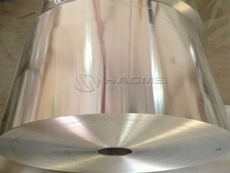
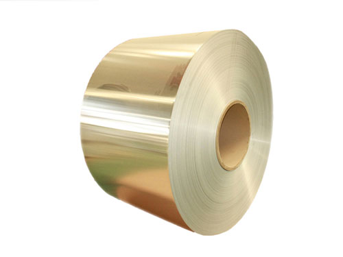
When high speed data travels through kilometers of underground communication cables, the quiet hero is often an ultra thin layer of aluminum foil. It is easy to describe aluminum foil as a simple barrier, but in underground networks it becomes a carefully engineered electromagnetic and chemical interface. From alloy selection and temper control to surface chemistry and lamination behavior, every detail of this foil determines whether a buried cable will perform flawlessly for decades or quietly degrade in the soil.
Why aluminum foil matters more underground than in aerial cables
Underground communication cables live in a harsh, uncontrolled environment. Moisture, soil ions, stray currents, lightning induced surges, and compacted backfill all try to attack the cable. In this context, aluminum foil is not only an EMI shield. It serves as
- A continuous Faraday cage that reduces both incoming and outgoing radiation
- A low impedance return path for induced currents and fault currents
- A moisture diffusion barrier when combined with polymers and flooding compounds
- A galvanic interface that must coexist with copper, steel, and other metals in the cable structure
Underground routes are far more exposed to ground potential rise, induced voltages from nearby power cables, and corrosion sources. As a result, the foil must be engineered with a tighter focus on electrical continuity, chemical stability, and compatibility with the cable’s composite structure than in standard indoor or aerial applications.
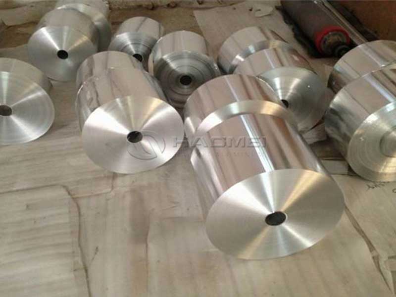
Alloy selection as a compromise between conductivity, strength, and formability
For communication cable shielding, the aluminum foil needs three core capabilities. It must conduct efficiently, wrap and fold without tearing, and resist cracking through decades of micro movement and thermal cycling in the ground.
Cable designers typically favor non heat treatable, work hardenable alloys with high aluminum content. The most common choices include
1050, 1060, 1070
Essentially pure aluminum alloys with aluminum content above 99.5 percent. They offer excellent electrical conductivity and good corrosion resistance. However, they can be relatively soft, so temper selection and any backing material such as polyester become crucial.1100
A commercially pure alloy with slightly higher strength than 1050 while retaining good conductivity and corrosion resistance.8011
An aluminum iron silicon alloy widely used in foil applications. It offers better strength and formability than pure aluminum, slightly lower conductivity, and very good rolling performance for thin foil gauges.
The tradeoff is clear. Higher purity improves conductivity and corrosion resistance but reduces strength. Alloy 8011 and similar compositions step in when the foil must survive mechanical loads during cable manufacturing, armoring, or tight bend installations, especially in ducts with high pulling tension.
Typical alloy and temper options for underground communication cable foil
To ground the discussion, here is a representative set of alloy temperament combinations and baseline properties often considered for cable shielding aluminum foil. Actual values vary by manufacturer and specification, but the table illustrates how alloy and temper shape the performance envelope.
Typical alloy, temper, and physical property ranges
| Alloy | Common Temper | Thickness Range mm | Tensile Strength MPa | Elongation percent | Electrical Conductivity percent IACS | Density g/cm3 |
|---|---|---|---|---|---|---|
| 1050 | O, H18, H24 | 0.010 to 0.080 | 60 to 110 | 15 to 35 | 60 to 62 | 2.70 |
| 1060 | O, H18, H24 | 0.010 to 0.080 | 65 to 115 | 15 to 35 | 61 to 63 | 2.70 |
| 1100 | O, H18, H24 | 0.010 to 0.080 | 80 to 135 | 10 to 30 | 55 to 59 | 2.71 |
| 8011 | O, H18, H22, H24 | 0.009 to 0.060 | 90 to 150 | 8 to 25 | 45 to 52 | 2.71 |
From the viewpoint of an underground cable designer, the choice might look like this
- Use 1050 or 1060 if the design prioritizes lowest possible shield resistance for high pair counts and very long transmission distances.
- Use 8011 where mechanical robustness, foldability, and crease resistance matter more, especially when combined with longitudinal corrugation, steel armoring, or repeated bending.
The effect of temper on underground performance
Temper is often misunderstood as a purely mechanical property classification, but in cable shielding it directly translates into electrical reliability and long term survivability in the soil.
Soft temper O
- High elongation allows tight wrapping over multi layer cable cores without micro cracking.
- Particularly beneficial for large diameter or complex core designs and for cables installed in ducts with frequent bends.
- More tolerant of thermal expansion mismatch between aluminum and polymer layers over the operating temperature range, often from about minus 40 to plus 80 degrees Celsius.
Hard tempers H18, H24, H22
- Improved tensile strength supports thinner foils, reducing metal usage and cable weight while maintaining handling integrity.
- Better crease retention is helpful where the foil must stay tightly wrapped during jacketing and armoring steps.
- Slightly higher susceptibility to crack initiation if over bent or stressed beyond design limits, hence the integration with polyester backing or controlled corrugation is common.
Underground, thermal cycling and soil movement are unavoidable. A foil that is too hard can develop micro fractures at bends and overlaps, compromising both EMI shielding and water barrier performance. For that reason, many underground designs favor intermediate or soft tempers, and rely on composite constructions such as aluminum polyester laminates to deliver the necessary mechanical resistance.
Implementation standards and relevant test frameworks
The performance of aluminum foil in underground communication cables is implicitly and explicitly governed by a web of international and regional standards. While many of these address the finished cable rather than the foil itself, they strongly influence foil specification.
Examples of widely referenced standards and requirements include
- IEC 61156 series for balanced communication cables
- IEC 60794 series for optical fiber cables, including duct and direct burial designs where aluminum foil shields may be used in hybrid or composite constructions
- IEC 60228 for conductor resistance, indirectly affecting shield design to manage induced currents
- Various EN, TIA, and ASTM standards that cover metallic shields, corrosion resistance, and flammability performance
Within these frameworks, the foil must help the cable meet metrics such as
- Transfer impedance and screening attenuation over specified frequency ranges
- Dielectric performance when the shield is integrated with inner insulating and jacketing polymers
- Long term aging performance under water immersion, damp heat, and corrosive soil conditions
- Mechanical tests such as repeated bending, torsion, crush, and tensile strength of the completed cable
Electrical parameters that matter for underground cable shielding
Signal integrity underground is dominated by crosstalk, attenuation, ground noise, and external interference. Aluminum foil helps manage these through several parameters.
Shielding effectiveness
Shielding effectiveness in decibels depends on the foil thickness, conductivity, overlap, and the presence of backing materials. A continuous aluminum foil with proper overlap can easily provide high attenuation over a wide frequency spectrum, particularly effective against electric field coupling and high frequency interference.
Transfer impedance
For metallic shields, transfer impedance in milliohms per meter is a parameter. It links shield design to the magnitude of interference currents and induced voltages. Low transfer impedance is achieved by
- Using continuous foil rather than only a braided shield
- Ensuring tight longitudinal overlap, often around 20 to 25 percent for reliability
- Choosing an alloy and thickness that provide low DC resistance per unit length
Ground path continuity
Underground cables often run in parallel with power lines or along electrically noisy routes. The aluminum foil shield can be used as a path to drain induced currents to ground. For this to work reliably
- Foil must retain electrical continuity around the entire circumference of the cable
- Joints, splices, and terminations must maintain foil to drain wire connections and ensure low resistance contact even after years of corrosion exposure
- The alloy must be compatible with the grounding hardware, often copper based, to limit galvanic potential differences
Typical electrical parameter ranges for aluminum foil used in cable shielding
To illustrate, here are example values for bare aluminum foil performance parameters commonly considered in design calculations.
| Property | Typical Range or Value | Notes |
|---|---|---|
| Thickness | 0.012 to 0.050 mm | Thinner foils possible with laminate support |
| Surface resistivity | 3 to 5 micro ohm per square for pure alloys | Depends on alloy conductivity and thickness |
| Volume resistivity | About 2.8 to 3.0 micro ohm cm | For high purity aluminum |
| Shield DC resistance per meter | Approx. 0.5 to 3 milliohm per meter | Varies with thickness, circumference, and alloy |
| Temperature coefficient of resistance | About 0.0039 per degree Celsius | Important for long lines and varying soil temperatures |
These characteristics define how the shield behaves when subject to power frequency coupling, lightning induced surges, and high frequency interference from radio and cellular systems.
Chemical and corrosion behavior in the buried environment
The underground world is chemically complex. Moisture, dissolved salts, sulfur compounds, and stray currents combine to challenge metallic components. Aluminum foil, however, has a distinctive self defending feature. It naturally forms a thin, adherent aluminum oxide layer that dramatically slows further corrosion in many conditions.
Still, the actual corrosion performance depends on
- Alloy composition, particularly iron and silicon content that can subtly influence pitting behavior
- pH and chloride content of the surrounding soil or water
- Presence of galvanic couples with copper conductors or steel strength members
- The integrity of polymer jackets and water blocking elements that should keep aggressive species away from the foil
To fully respect the chemical complexity, aluminum foil suppliers for underground applications typically control impurity levels tightly. Here is a representative chemical composition table for two commonly used foil alloys in shielding.
Typical chemical composition of aluminum foil alloys for cable shielding
Values are indicative ranges in weight percent.
| Element | 1050 Alloy wt percent | 8011 Alloy wt percent | Function and impact |
|---|---|---|---|
| Aluminum Al | 99.50 min | Balance, typically 97.0 to 99.0 | Base metal providing conductivity and corrosion resistance |
| Silicon Si | 0.25 max | 0.40 to 0.80 | Improves strength and foil rolling behavior in 8011, may slightly lower conductivity |
| Iron Fe | 0.40 max | 0.60 to 1.0 | Strengthening, influences recrystallization and foil surface morphology |
| Copper Cu | 0.05 max | 0.10 max | Excessive copper can increase susceptibility to some corrosion modes |
| Manganese Mn | 0.05 max | 0.10 max | Minor strengthening effect |
| Magnesium Mg | 0.05 max | 0.05 max | Very low levels to preserve conductivity |
| Zinc Zn | 0.05 max | 0.10 max | Typically kept low to avoid corrosion concerns |
| Titanium Ti | 0.03 max | 0.08 max | Grain refinement and control of recrystallization |
| Other, each | 0.03 max | 0.05 max | Tight control to stabilize surface behavior |
| Others, total | 0.15 max | 0.15 max | Sum of all minor impurities |
This chemical landscape shapes how the foil responds to the external world. For instance
- The fine balance of iron and silicon in 8011 optimizes rolling to ultra thin gauges without pinholes, essential for reliable shielding.
- The low copper content protects against specific forms of localized corrosion that could occur in chloride containing soils.
- The tight limit on volatile impurities helps ensure stable adhesion to polymers during lamination and avoids gas formation in high temperature cable processes.
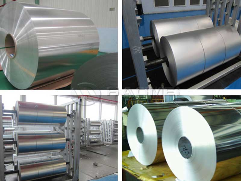
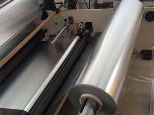
Laminated foil constructions as an engineered interface
In modern underground communication cables, aluminum foil rarely appears alone. It is commonly bonded to polyester or other polymer films to create aluminum polyester AL PET or aluminum polyester aluminum AL PET AL tapes. These laminates turn the foil into an engineered interface between metal and insulation.
Benefits of laminating include
- Enhanced tear resistance and handling strength during high speed cable production lines
- Controlled adhesion to ensure the foil stays where it is placed, maintaining overlap and coverage through the whole service life
- Improved moisture barrier performance due to the combined effect of metal and polymer layers
- Electrical isolation between the aluminum and the core or other metallic components where needed to manage galvanic effects
From a unique viewpoint, the laminate behaves like a composite electromagnetic skin. The aluminum layer delivers conductivity and reflectivity for EMI control. The polyester film stabilizes the geometry and surface, smoothing out micro mechanical stresses that could otherwise crack the foil during bending, temperature cycling, and soil loading.
parameters for laminated aluminum foil tapes
For underground cable applications, designers pay attention to laminate traits such as
- Total thickness of metal plus film, balancing flexibility and barrier performance
- Peel strength between aluminum and polymer, preventing delamination in wet, warm environments
- Thermal shrinkage of the film, which can place stress on the foil layer at elevated temperatures
- Compatibility with hot melt adhesives, flooding compounds, and jacketing materials such as polyethylene or PVC
The interplay of mechanical and electrical design
One of the distinctive engineering challenges lies in aligning the mechanical behavior of the foil with the electromagnetic goals of the shield.
Consider these intertwined aspects
- Minimum bending radius of the completed cable must not induce plastic deformation beyond the foil’s strain capability. Hard tempers may give excellent neatness during production but are unforgiving if the cable is installed with tight bends.
- Longitudinal overlap of the foil is chosen to ensure consistent electrical continuity, but this overlap also introduces a local stiffness irregularity that can influence how the cable flexes.
- In multi layer shields, such as foil plus braid or foil plus corrugated metal tape, the aluminum foil must cooperate with more rigid components to share stress rather than concentrate it in a brittle zone.
For underground installations, where soil compaction and settlement slowly press against the cable, this mechanical electromagnetic pairing is critical. A mechanically well balanced shield maintains its integrity, and with it the stable impedance profile that keeps signal performance predictable over decades.
Thermal considerations in buried environments
Buried cables are subject to seasonal thermal cycles and local hotspots near power lines or industrial infrastructure. Aluminum foil responds to temperature in several ways that matter for system design.
- Thermal expansion mismatch with polymers can generate shear stresses at the interface. Proper temper selection and laminate design mitigate this.
- Electrical resistance increases with temperature, potentially affecting shield current distribution during transient events. Cable designers consider the worst case soil temperature when calculating shield temperature rise under fault or surge conditions.
- Foil oxidation may slightly accelerate at elevated temperatures in the presence of moisture, but the stable oxide layer generally restricts deep penetration.
Viewed from a long term reliability perspective, the foil is part of the cable’s thermal ecosystem, not just its electromagnetic shell. Its behavior under temperature fluctuations must harmonize with every other element from conductor insulation to outer sheath.
Integrating aluminum foil into holistic underground cable design
The most successful underground communication cables treat aluminum foil not as a commodity layer but as a strategic component that intersects multiple design domains.
Electrical domain
- Optimizes shielding effectiveness across the relevant spectrum, supporting modern high data rate and low noise requirements.
- Provides predictable, low resistance paths for transient and induced currents, integrated with grounding and bonding strategies.
Mechanical domain
- Maintains continuity after installation stresses, soil settling, and thermal cycling.
- Works with armoring and jacketing to keep the cable flexible enough for real world routing while robust against crush and impact.
Chemical domain
- Resists corrosion in a wide variety of soils, enhanced by robust jacketing and water blocking systems.
- Maintains strong adhesion in laminates despite exposure to moisture, heat, and potential chemical contaminants.
Manufacturing domain
- Processes efficiently in high speed slitting, taping, and cabling lines with minimal wrinkling or tearing.
- Keeps thickness and mechanical properties consistent to avoid variations in cable electrical performance and dimensional stability.
When designers and material specialists view aluminum foil through all these lenses simultaneously, they unlock the real value of this ultra thin metal layer. It becomes a finely tuned interface that quietly guarantees signal integrity in some of the most challenging environments for cable infrastructure.