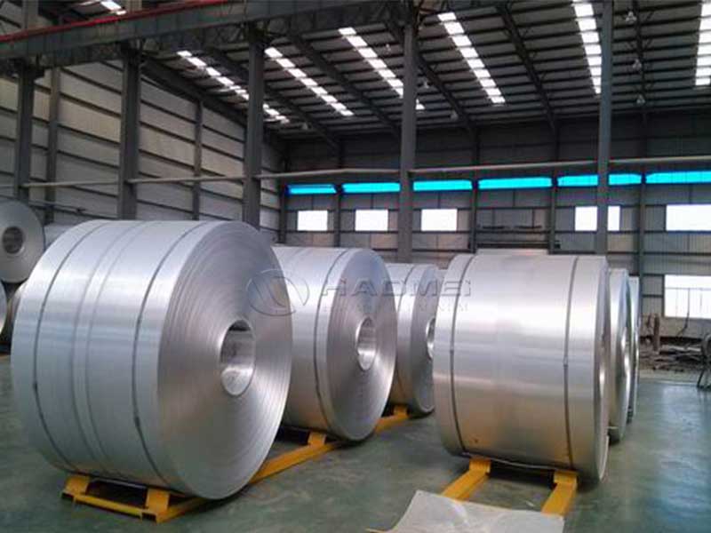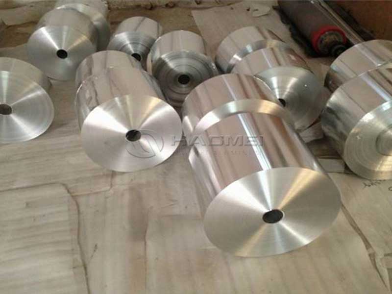
Battery tab aluminum foil for electric vehicles is often described in terms of conductivity, thickness, and cost. That view is accurate, but incomplete. The real story begins at the microscopic level, where alloy design, surface chemistry, and temper control quietly dictate how efficiently electrons and heat move through every battery cell, kilometer after kilometer.
From this perspective, battery tab foil is not just a conductor; it is the negotiator between electrochemistry and power electronics, between the fragile, highly reactive internal environment of the cell and the harsh, vibration‑filled, thermally stressful world of the vehicle. Low impedance is the headline target, but the path to it runs through subtle choices in aluminum alloy composition, processing routes, and implementation standards.
Why Low-Impedance Battery Tab Foil Matters More Than Ever
In modern EV packs, current densities through tabs are climbing as fast‑charging and high-power acceleration become mainstream. Every micro-ohm of resistance forces the system to pay an invisible tax in the form of:
- Additional joule heating at current collectors
- Uneven current distribution between parallel cells
- Higher temperature gradients across the pack
- Reduced energy efficiency and usable range
Aluminum foil for battery tabs must therefore serve multiple roles simultaneously:
- Provide ultra-low electrical resistance over millions of charge–discharge cycles
- Manage thermal load without hot spots at welds and connections
- Maintain mechanical integrity through vibration, swelling, and compression
- Preserve interfacial stability with active electrode coatings and busbars
Low impedance is not just a value on a datasheet; it is the sum of alloy purity, surface condition, oxide behavior, and mechanical consistency, from the rolling mill to the final weld.
A Distinctive View: Impedance as a Materials-Ecosystem Property
Rather than treating tabs as isolated parts, consider impedance as a property of a whole ecosystem:
- The foil’s bulk resistivity
- The stability and thickness of the native oxide layer
- The surface roughness and cleanliness at microscopic contact points
- The welding metallurgy with copper, nickel, and plated steel components
- The stress state introduced by tempering and slitting
In this ecosystem, even trace elements at parts-per-million levels influence how electron pathways form, how oxide films heal after welding, and how contact resistance evolves during the life of the pack. Low impedance is won or lost where crystallography, chemistry, and processing intersect.
Alloy Choices: Why “Pure” Aluminum Is Not a Simple Concept
For EV battery tab applications, high-purity aluminum alloys such as 1050, 1060, 1070, and 1100 dominate, but “purity” is a carefully engineered compromise rather than an absolute ideal.
- Higher purity (for example 1070, 99.7% Al) reduces bulk resistivity and slightly improves thermal conductivity
- Slightly alloyed grades (for example 1100 with controlled Fe and Si) improve strength and formability without severely penalizing conductivity
- Ultra-low copper content is essential to minimize corrosion and preserve long-term impedance stability in moist or salty environments
Alloy & Chemical Properties: Typical Data for EV Battery Tab Foil
The following table summarizes representative properties of common aluminum alloys used for EV battery tab applications. Values are indicative and may vary by producer and temper.
| Property | 1050 (H18) | 1060 (H16/H18) | 1070 (H18) | 1100 (H18) |
|---|---|---|---|---|
| Typical Al content (wt%) | ≥ 99.50 | ≥ 99.60 | ≥ 99.70 | ≥ 99.00 |
| Main impurities (wt%) | Fe ≤ 0.40, Si ≤ 0.25 | Fe ≤ 0.35, Si ≤ 0.25 | Fe ≤ 0.25, Si ≤ 0.20 | Cu 0.05–0.20, Fe+Si ≤ 0.95 |
| Density (g/cm³) | ~2.70 | ~2.70 | ~2.70 | ~2.71 |
| Electrical conductivity (% IACS) | ~60–61 | ~61–62 | ~62–63 | ~57–58 |
| Resistivity at 20°C (µΩ·cm) | ~2.85–2.80 | ~2.80–2.75 | ~2.75–2.70 | ~3.00–2.95 |
| Thermal conductivity (W/m·K) | ~220–230 | ~225–235 | ~230–240 | ~210–220 |
| Tensile strength (MPa) | ~110–140 (H18) | ~115–145 (H16/H18) | ~115–145 (H18) | ~120–160 (H18) |
| Yield strength (MPa) | ~95–130 | ~100–135 | ~100–135 | ~110–145 |
| Elongation A50 (%) | ~1–5 | ~1–4 | ~1–4 | ~1–4 |
| Typical thickness for tabs (µm) | 8–30 | 8–30 | 8–25 | 10–30 |
In practice, 1060 and 1070 offer an attractive combination of very low resistivity and robust processing performance. 1100 is selected when a slight strength increment justifies a modest conductivity trade-off.
Tempering: Controlling Microstructure for Stable Low Impedance
Temper is often reduced to labels like O, H14, H16, or H18. From the viewpoint of impedance, temper is essentially a way to “tune” the internal structure of the foil:
- Soft temper (O): larger grains, low dislocation density, excellent formability, but lower strength and potential for deformation at high clamping pressures
- Half-hard tempers (H14, H16): balanced grain size and dislocation density; good mechanical stability and adequate formability
- Full-hard temper (H18): high strength, high dislocation density, stable dimensions, but limited formability and increased risk of cracking in tight bends
For EV battery tabs, H16 and H18 are particularly attractive. Their higher strength stabilizes the geometry of welded joints and busbar connections, helping maintain consistent contact pressure under vibration and thermal cycling. This mechanical stability quietly protects low impedance over the vehicle’s lifetime.
The processing sequence—continuous casting or direct chill casting, hot rolling, cold rolling, intermediate and final anneals—shapes texture and grain boundary character. A controlled, moderately strong cube texture, for instance, can reduce anisotropy in mechanical properties so that the foil responds similarly regardless of rolling direction, which again contributes to uniform stress distribution and contact performance in the pack.
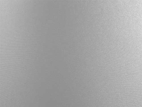
Surface Oxide and Contact Resistance: Where Chemistry Meets Electronics
Bare aluminum spontaneously forms an oxide layer in air. This alumina film is thin—typically 2 to 5 nm on freshly processed foil—but its electrical behavior under compression and in the presence of electrolyte vapors is crucial.
From a distinctive technical viewpoint, the tab’s interfacial impedance is governed by a layered structure:
- The bulk aluminum alloy, setting baseline resistivity
- A transition zone containing segregated impurities and nano-precipitates at the surface
- The native oxide layer composed primarily of Al₂O₃ with traces of hydroxides and absorbed species
- The counter-surface (for example Cu busbar, Ni-plated steel, or another Al foil)
Mechanical pressure and welding transform this stack. Under welding heat, oxide disrupts, flows, and partially dissolves into molten regions; upon cooling, new oxide grows. Minimizing impedance thus requires a foil whose chemistry and surface condition:
- Limits thick, porous, or hydrated oxide growth
- Maintains a smooth but finely structured surface to maximize real contact area
- Remains clean of rolling oils, chloride residues, and particulates
Producers achieve this through tightly controlled degreasing, surface activation, and passivation processes. The “invisible cleanliness” of the foil is often more important for impedance than marginal differences in bulk conductivity between 1060 and 1070.
Typical Parameters for EV Battery Tab Aluminum Foil
Battery manufacturers define compact but stringent windows for parameters. The following ranges are typical for low-impedance EV tab foil, with variations according to specific cell design and pack architecture.
Alloy designation
- High-purity series: 1050, 1060, 1070, 1100
- Optional Cu/Al hybrid concepts for specialized busbar interfaces
Temper
- H14, H16, H18 for prismatic and pouch EV cells
- Soft temper O for special fold or flex-demanding designs
Thickness
- About 8–15 µm for high-energy-density cells seeking weight reduction
- About 15–30 µm for high-power cells prioritizing robustness
Width tolerances
- Typically ±0.1 mm for narrow tabs
- Tighter tolerances achievable depending on slitting technology and coil stability
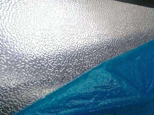
Surface condition
- Ra often in the 0.2–0.6 µm range, tuned to welding process and adhesive systems
- Clean, oil-free, with residual rolling lubricant controlled below strict ppm thresholds
Flatness and shape
- Minimal camber and edge wave to prevent misalignment and local pressure peaks
These seemingly simple ranges are the distilled result of balancing thermal, electrical, and mechanical criteria in a tightly coupled system.
Implementation Standards: From Foil Mill to EV Pack
EV manufacturers lean on both general aluminum standards and battery-specific specifications. While many internal standards remain proprietary, several public frameworks and practices underpin advanced tab foil production:
Base material standards
- EN AW-1050A / 1060 / 1070 / 1100 for composition limits
- ASTM B209/B928 or EN 485 series as reference for mechanical properties and tolerances
Battery application standards and guidelines
- Alignment with IEC 62660 series for performance and reliability of secondary lithium cells
- Integration into automotive quality frameworks such as IATF 16949 and ISO 9001
- Compliance with RoHS and REACH for hazardous substance restrictions
Internal OEM and cell-maker specifications
- Maximum allowable DC contact resistance of tab-to-busbar joint
- Acceptable weld nugget geometry and minimum weld cross-sectional area
- End-of-line impedance checks at cell and module level
The foil producer’s role is to translate these sometimes high-level requirements into measurable material parameters: composition windows, temper ranges, roughness envelopes, cleanliness targets, and coil-to-coil consistency metrics.
Chemical Composition: Typical Limits for Tab Foil Alloys
Representative chemical composition windows for common alloys used in EV battery tabs are shown below. All values in weight percent; aluminum is the balance.
| Element | 1050 (typical limits) | 1060 (typical limits) | 1070 (typical limits) | 1100 (typical limits) |
|---|---|---|---|---|
| Si | ≤ 0.25 | ≤ 0.25 | ≤ 0.20 | ≤ 0.95 (Si+Fe total) |
| Fe | ≤ 0.40 | ≤ 0.35 | ≤ 0.25 | |
| Cu | ≤ 0.05 | ≤ 0.05 | ≤ 0.04 | 0.05–0.20 |
| Mn | ≤ 0.05 | ≤ 0.03 | ≤ 0.03 | ≤ 0.05 |
| Mg | ≤ 0.05 | ≤ 0.03 | ≤ 0.03 | ≤ 0.05 |
| Zn | ≤ 0.07 | ≤ 0.05 | ≤ 0.04 | ≤ 0.10 |
| Ti | ≤ 0.03 | ≤ 0.03 | ≤ 0.03 | ≤ 0.05 |
| Others (each) | ≤ 0.03 | ≤ 0.03 | ≤ 0.03 | ≤ 0.05 |
| Others (total) | ≤ 0.10 | ≤ 0.10 | ≤ 0.10 | ≤ 0.15 |
| Al (min) | ≥ 99.50 | ≥ 99.60 | ≥ 99.70 | ≥ 99.00 |
These limits are not arbitrary. Reduced Fe and Si support higher conductivity and more uniform oxide behavior. Tight Cu control reduces galvanic vulnerability when coupled with copper components in humid, ion-rich environments typical of battery packs.
Designing for Low Impedance Across the Entire Current Path
For an EV designer, it is not enough to specify “high-conductivity aluminum foil.” Low impedance must be preserved across each segment of the current path:
- From active material to aluminum current collector
- From collector to tab foil—including any laser-scribed or micro-perforated sections
- From tab to busbar or terminal lug through welds or mechanical crimps
- From module connectors to the pack’s power electronics
Battery tab aluminum foil sits mainly in the second and third link of this chain. Its contribution to overall impedance comes from:
- Bulk resistivity, proportional to thickness and length of the tab
- Contact resistance at welded or clamped interfaces
- Degradation of those interfaces under cycling, vibration, and corrosion
By specifying appropriate alloy and temper, controlling surface chemistry, and ensuring dimensional consistency, foil producers help engineers achieve high C-rate capability with manageable heat generation and minimal power loss.
Welding, Joining, and the Metallurgical Dialogue with Copper
Most EV architectures require aluminum tabs to interface with copper busbars or collector plates. This dissimilar metal junction introduces a fascinating metallurgical challenge: how to create a robust, low-impedance bond between metals that prefer not to mix extensively.
Laser, ultrasonic, and resistance welding techniques each interact differently with aluminum’s oxide layer and copper’s high thermal conductivity. An optimized tab foil supports these processes by offering:
- Predictable melt behavior through narrow composition control
- Consistent surface thickness and roughness to stabilize energy absorption in the weld zone
- Adequate strength in H16/H18 tempers to avoid tearing at weld boundaries
When executed correctly, the aluminum tab does more than conduct. It acts as a stress-distribution layer between stiff copper components and more compliant cell cans or pouches, smoothing mechanical loads and protecting the integrity of low-impedance joints over time.
Thermal Management: Using Foil as a Heat Conduit, Not a Hotspot
Low electrical impedance is closely intertwined with thermal behavior. Every watt of resistive loss from the tab becomes heat that must be dissipated. High-purity aluminum, with thermal conductivity often near or above 230 W/m·K, functions as a lateral heat spreader, redistributing localized hot spots away from welds and interfaces.
Through carefully engineered thickness and alloy selection, the foil:
- Reduces thermal gradients along current paths
- Lowers peak temperatures at high-current events such as fast charging or regenerative braking
- Helps minimize thermal stress in sealants, adhesives, and polymeric cell components
A Holistic View for EV Engineers and Materials Teams
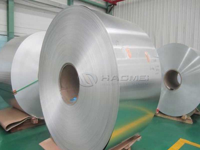
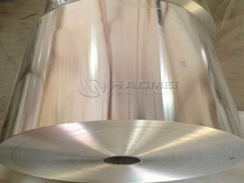
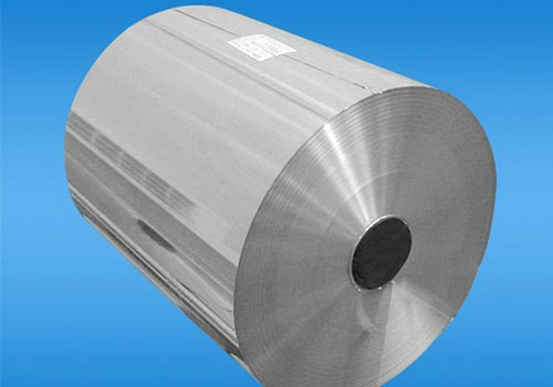
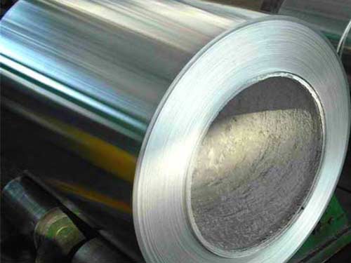
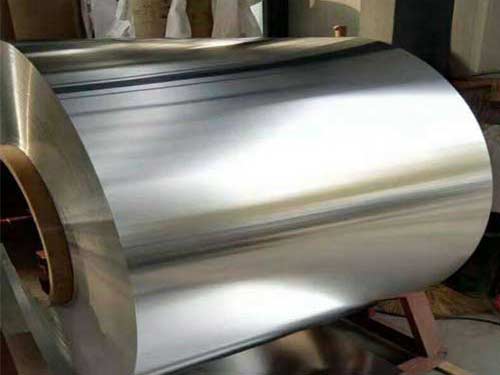
From a high-level engineering perspective, battery tab aluminum foil looks like a commodity: thin, shiny metal on a coil. From the vantage point of materials science and EV powertrain efficiency, it is a precisely tuned interface material whose microscopic features ripple outward into macroscopic outcomes:
- Lower pack impedance and higher energy efficiency
- Cooler operation during fast charge and aggressive driving
- More consistent cell balancing and longer cycle life
- Greater design freedom in busbar layout and terminal configuration
By treating tab foil as part of an integrated materials ecosystem—where alloy composition, temper, surface chemistry, and process routes are co-optimized—EV manufacturers unlock incremental gains that accumulate into clear competitive advantages.
Battery tab aluminum foil with genuinely low impedance is not just the result of high-purity aluminum. It is the outcome of deliberate design, rigorous implementation standards, and a deep appreciation for the quiet but decisive role that a few micrometers of metal play in every electric vehicle on the road.